Getting Started with Your LED Display Project
Are you excited to explore the world of Arduino with a hands-on project that combines creativity and electronics? This comprehensive guide walks you through creating a stunning 20 LED light display that will amaze your friends and family. Whether you're new to Arduino or looking to expand your skills, this project offers the perfect opportunity to learn about circuit design, programming, and creating beautiful light patterns.
Before we jump into the building process, let's talk about why this project matters. Working with multiple LEDs teaches you about parallel circuits, current management, and programming logic. The skills you gain here will serve as a foundation for more complex projects like LED matrices, mood lighting systems, or even custom signage. The best part? You can see your code come to life in real-time as the lights respond to your programming commands.
Handy Tools For You
Essential Materials and Tools
To ensure your project goes smoothly, gather all necessary components before starting. Here's what you'll need:
- Arduino Uno or compatible board: The brain of your operation
- 20 LEDs of your chosen color(s): Consider mixing colors for more visual interest
- 20 resistors (220-330 ohm): Crucial for protecting your LEDs from excessive current
- Large breadboard: Provides ample space for organizing your circuit
- Jumper wires: Both male-to-male and male-to-female types for flexible connections
- USB cable: For connecting your Arduino to your computer
- Computer with Arduino IDE installed: Your programming workstation
When selecting your components, pay special attention to LED quality. Brightness levels can vary between manufacturers, so if visual consistency matters for your project, consider purchasing LEDs from the same batch. For resistors, 220-330 ohm values work well for most standard LEDs when using Arduino's 5V output.
Circuit Assembly and Wiring Strategy
Building a reliable circuit is crucial for your 20 LED display. Follow this systematic approach to ensure success:
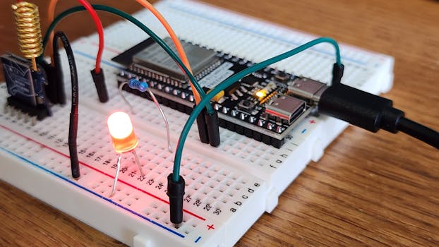
Begin by placing your breadboard in a comfortable working position. Insert the 20 LEDs in rows, paying attention to polarity. The longer leg (anode) should face the positive side, while the shorter leg (cathode) connects to ground. For organization, consider arranging LEDs in patterns - perhaps four rows of five LEDs each, or a circular arrangement depending on your creative vision.
Connect a resistor to each LED's anode (long leg). This step cannot be skipped - without resistors, your LEDs will draw too much current and burn out quickly. The resistors limit current flow to safe levels, ensuring your components last.
Now for the wiring: Connect all cathode (short) legs together in a common ground bus. Run a wire from this ground bus to one of the Arduino's GND pins. For the positive sides, connect each resistor to individual digital pins on the Arduino. Since you're using 20 LEDs, you'll need 20 digital pins. The Arduino Uno has exactly 20 digital I/O pins (0-13 and A0-A5 when used as digital), making it perfect for this project.
Double-check your connections before proceeding. A common mistake is reversing LED polarity or missing resistor connections. Use a multimeter to verify continuity if you have one available.
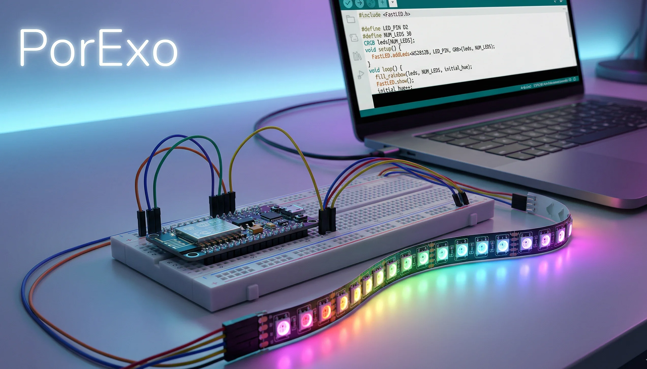
Programming Your Light Patterns
The real magic happens when you start programming. The Arduino IDE makes it straightforward to control your LED display. Here's a basic framework to get you started:
// Define LED pin connections
int ledPins[] = {2,3,4,5,6,7,8,9,10,11,12,13,A0,A1,A2,A3,A4,A5};
int totalLEDs = 20;

void setup() {
  // Initialize all LED pins as outputs
  for(int i = 0; i < totalLEDs; i++){
    pinMode(ledPins[i], OUTPUT);
  }
}

void loop() {
  // Simple sequential pattern
  for(int i = 0; i < totalLEDs; i++){
    digitalWrite(ledPins[i], HIGH);
    delay(100);
    digitalWrite(ledPins[i], LOW);
  }

  // All LEDs blink together
  for(int i = 0; i < 5; i++){
    for(int j = 0; j < totalLEDs; j++){
      digitalWrite(ledPins[j], HIGH);
    }
    delay(200);
    for(int j = 0; j < totalLEDs; j++){
      digitalWrite(ledPins[j], LOW);
    }
    delay(200);
  }
}
This code provides two basic patterns: a sequential light chase and a synchronized blink. Upload this to your Arduino using the USB cable. The upload process typically takes 10-30 seconds. Once complete, your LEDs should spring to life with the programmed patterns.
Experiment with modifying the code to create your own patterns. Try changing delay times, creating alternating sequences, or programming specific shapes and animations. The possibilities are limited only by your imagination and programming skills.
Taking Your Display to the Next Level
Once you have the basic display working, consider these enhancements to make your project stand out:
Add interactive elements by incorporating sensors. A potentiometer could control animation speed, while a light sensor might adjust brightness based on ambient light conditions. You could even add push buttons to cycle through different pattern modes.
Explore more complex programming techniques like arrays for storing custom patterns, or implement mathematical functions to create wave-like effects. For advanced users, consider using PWM (Pulse Width Modulation) on compatible pins to control LED brightness and create fading effects.
If you want to preserve your project permanently, consider transferring the circuit from the breadboard to a perfboard or custom PCB. This makes your display more durable and portable. You could even design and 3D print a custom enclosure to give your project a professional finish.
Frequently Asked Questions
Why do I need resistors for each LED?
Resistors limit the amount of current flowing through each LED. Without them, the LEDs would draw excessive current from the Arduino pins, potentially damaging both the LEDs and the Arduino board. Each LED needs its own resistor to ensure proper current regulation.
Can I use different colored LEDs in the same circuit?
Yes, you can mix LED colors, but be aware that different colored LEDs may have slightly different voltage requirements. Standard red, green, and yellow LEDs typically work fine with the same resistor values, but blue and white LEDs might require adjustments. Check the specifications for your specific LEDs.
What if I don't have enough digital pins on my Arduino?
If you need to control more LEDs than you have available pins, consider using shift registers like the 74HC595. These chips allow you to control multiple LEDs using only three Arduino pins, making it possible to drive dozens or even hundreds of LEDs with a single microcontroller.
My LEDs aren't lighting up - what should I check?
Start by verifying your wiring: ensure LEDs are oriented correctly (long leg to positive), resistors are properly connected, and all connections are secure. Check that your code is uploading successfully and that you're using the correct pin numbers in your program. Also confirm that your Arduino is receiving power via the USB connection.
How can I make my LED patterns more complex?
Experiment with nested loops, arrays to store pattern sequences, and mathematical functions to create interesting effects. You can also look into using libraries designed for LED control, or implement state machines to create sophisticated animation sequences that respond to user input or sensor data.